The problem

The protective conductors in systems with servo drives and frequency inverters is not currentless.
Various measures (use of line filters, shielded motor cables, etc.) must be taken in order to meet CE conformity and the binding protection goals of the low-voltage, EMC and machine directive. Cable shields, interference suppression capacitors and motor windings represent parasitic capacitances. In a fault-free system state, operational leakage currents flow through these parasitic capacitances to the protective conductor or via other conductive parts to the earth potential.
Manufacturers and operators of devices and systems are fundamentally obliged to protect people against electric shock and to switch off sources of danger that could cause fires. Exactly these hazards can be caused by fault currents and must therefore be included in the safety considerations.
For personal and fire protection in these systems, AC/DC sensitive residual current circuit breakers with rated residual currents of 30 mA are used. These rated residual currents are reached or even exceeded in many electrical systems during normal operation. In the past, the response to such problems was the impermissible expansion / bridging of the protective device or the lowering of the prescribed protective goals through the use of RCDs with higher rated residual currents (e.g. 300 mA instead of 30 mA).
Currents that are caused by insulation faults or by the human body (e.g. through contact) are fault currents. Only these currents should trigger the RCCB and lead to the shutdown of a system.
This important distinction between operational leakage currents on the one hand and fault currents due to human contact or insulation problems on the other hand cannot be made by today’s residual current protective devices. Therefore, unwanted shutdowns by the protective device very often occur without an actual fault. The consequences can be expensive downtimes and restart times as well as production scrap.
The solution

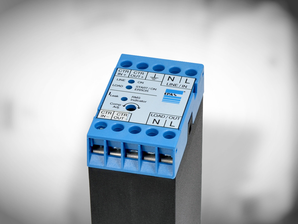
The leakage current compensation device LEAKCOMP® 1P is used in electrical systems or machines in which single-phase frequency inverters and/or SERVO controllers are to be operated on residual current devices (RCD) or residual current circuit breakers (RCCB).
The level of the compensation current can be set using a potentiometer in the front cover. The level of the compensation current can be increased by turning the potentiometer clockwise. With an optimal adjustment the compensated 50 Hz leakage current is almost zero. If the potentiometer is turned completely to the left, there is no compensation.
Leakage current peaks, which occur when the converter is switched on due to the charging of the capacitors, are prevented by the integrated soft start function.
The interchanging of phase and neutral conductor is recognized by LEAKCOMP® 1P during the start-up process and corrected if necessary.
The LEAKCOMP® 1P has three light-emitting diodes as display elements. The green LED serves as an operating indicator and signals the presence of mains voltage. During the soft start process, the red LED first flashes quickly (1st level) and then more slowly (2nd level). When the soft start process is complete, the red LED lights up continuously (operation). If an error occurs during the soft start process, the red LED flashes (see chapter “Troubleshooting”). The level of the leakage current is indicated by the yellow LED. The darker the yellow LED lights up, the lower the compensated leakage current. The yellow LED is therefore also used to manually adjust the compensation.
 Deutsch


